PowerPC Hardware

Version 2.0
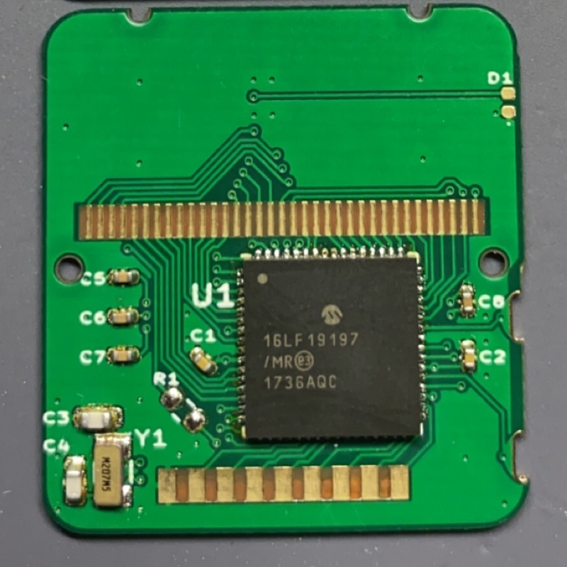
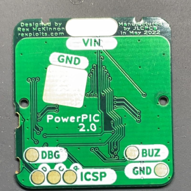
Their were several large changes in version 2.0:
- RTC Crystal - The biggest change in v2 was the addition of a 32.768kHz crystal to drive the pic’s RTCC module. This allows accurate timekeeping, as before we were using the internal oscillator’s 31.25kHz which caused a drift of +4:30 minutes every 24-hours. We also use the clock signal this crystal generates for the LCD and the main ‘tick’ timer.
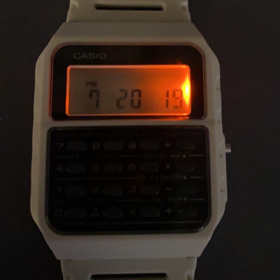
- LED Backlight - The brightest change is the addition of an LED backlight on the right side of the LCD display. It was placed in its current spot with minimal measurments and lots of ‘looks good’s, but it fits without effecting the LCD and provides a comparable amount of light to other Casio backlights.
- Button/ICSP Pins - The Mode and Adj buttons were switched to the pins used for the ICSP interface. Version 1 used these pins for LCD segments so programming caused a DC bias on some display segments if the LCD was connected. This also allows a secondary use of the programming testpoints - to simulate button presses during development.
- Keypad Column Pins - The column pins had to be remapped to make use of the XTAL pins.
- LCD Segment Pins - Some LCD segment pins had to be remapped.
- Microcontroller position - The pic was moved to the right side of the board to make use of a inset in the case.
These were again manufactured by JLCPCB, but this time I sprung for the ENIG finish. With the addition of the crystal, the clock drift is seconds a day without any calibration. Several LED options are going to be tested, right now I prefer a nice orange. Firmware is still very much a WIP, but a PowerPIC v2.0 is my daily driver.
Version 1.1
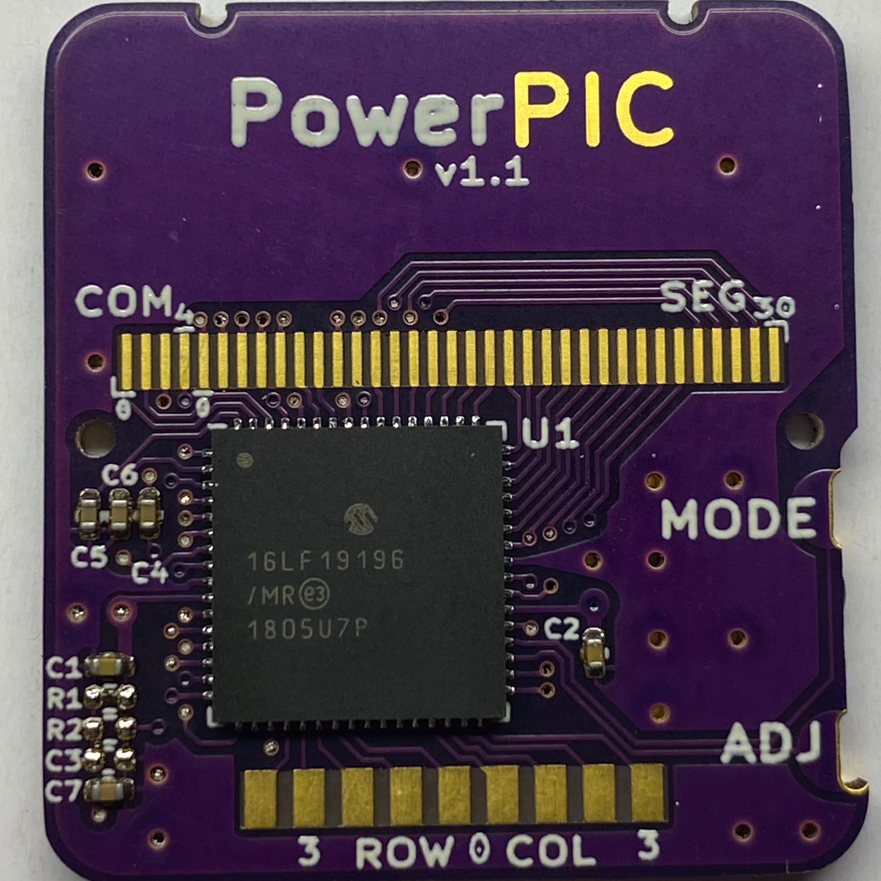
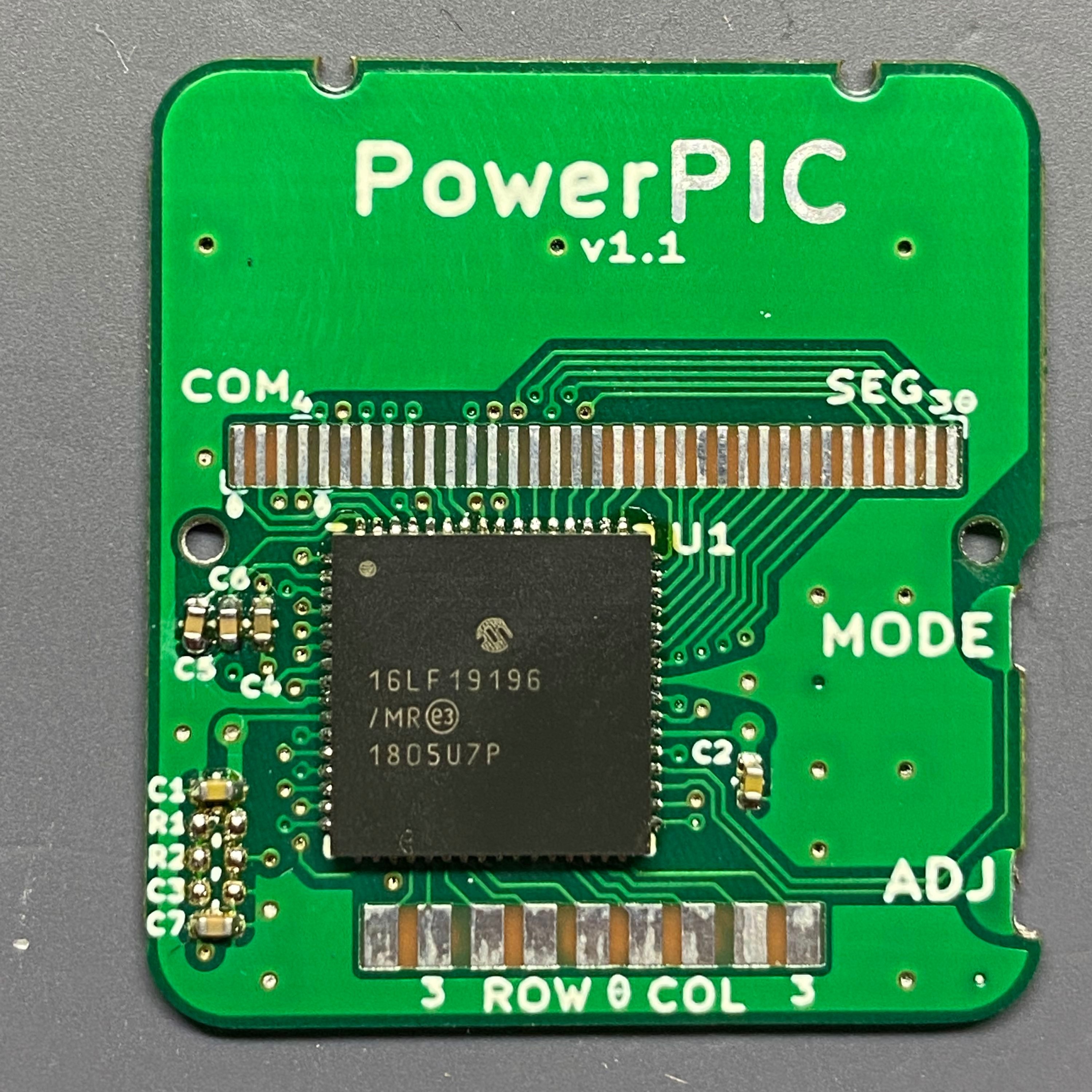
This revision of version addressed a couple problems the first board had:
- Keypad row pins - The pin orignally used for row 1 was RA5, which is unusable as an i/o pin because it is used for VBAT. I decided to remap all row pins to RA0-RA3.
- Buzzer output - The buzzer pin was changed to RG7 from RF0 since we need a PWM signal to drive the piezo buzzer.
- Test Points - Test points were added for the Mode and Adj buttons. An additional ground point was also added.
The first run of version 1.1 boards were manufactured by OSHPark using their standard service. Although these boards were also too thick, I could work more on firmware. At this point I began looking around for someone to make boards with the correct thickness I required (0.6mm) and found JLCPCB. The second run of boards were manufactured by them with that sweet HASL finish. These were the first boards that were the correct thickness, so I could finally put the watch together fully.
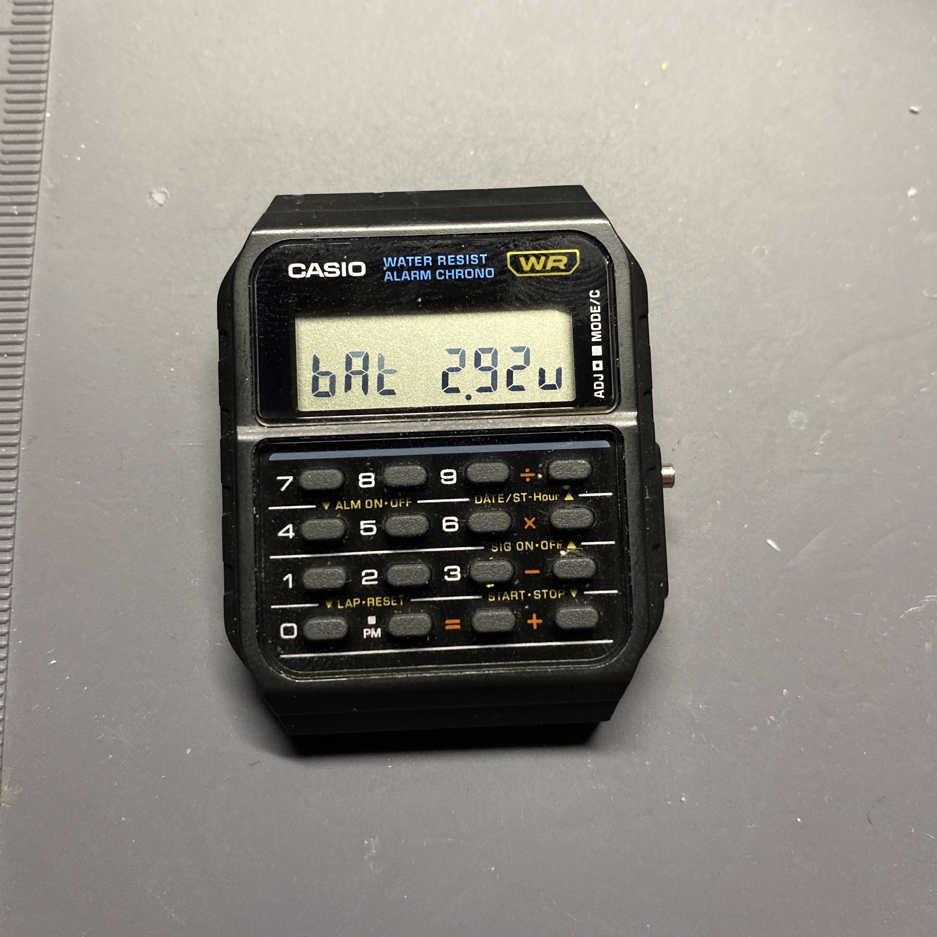
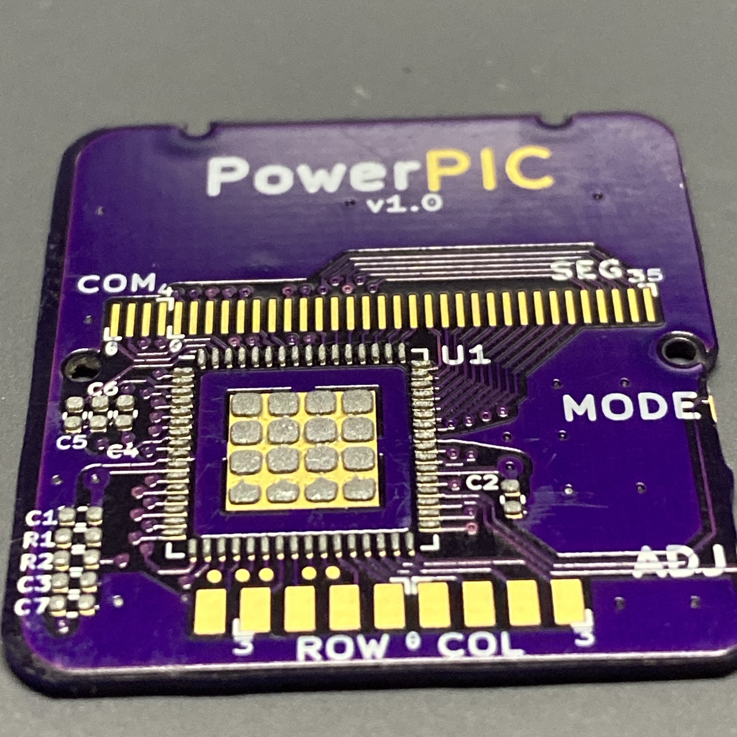
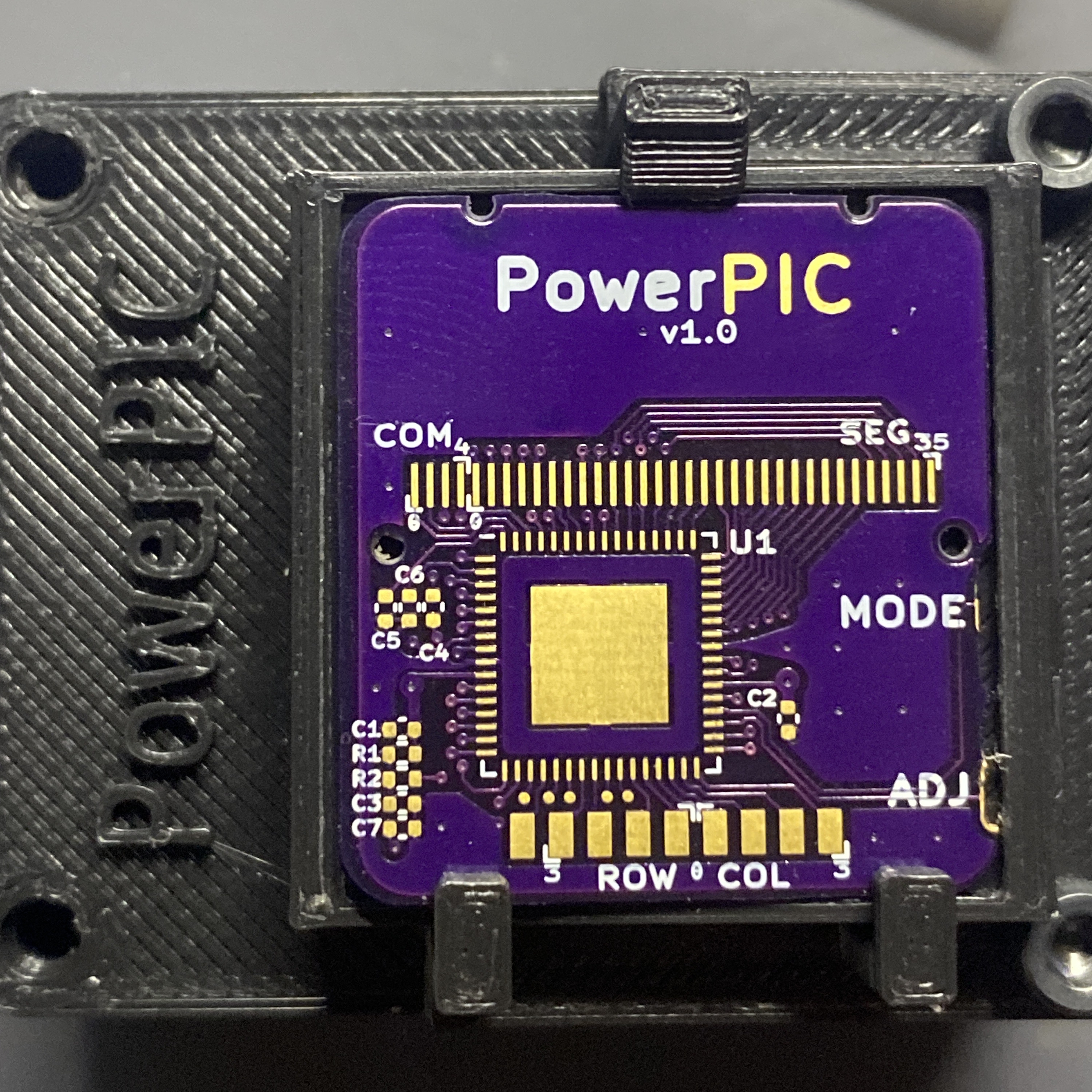
Version 1.0
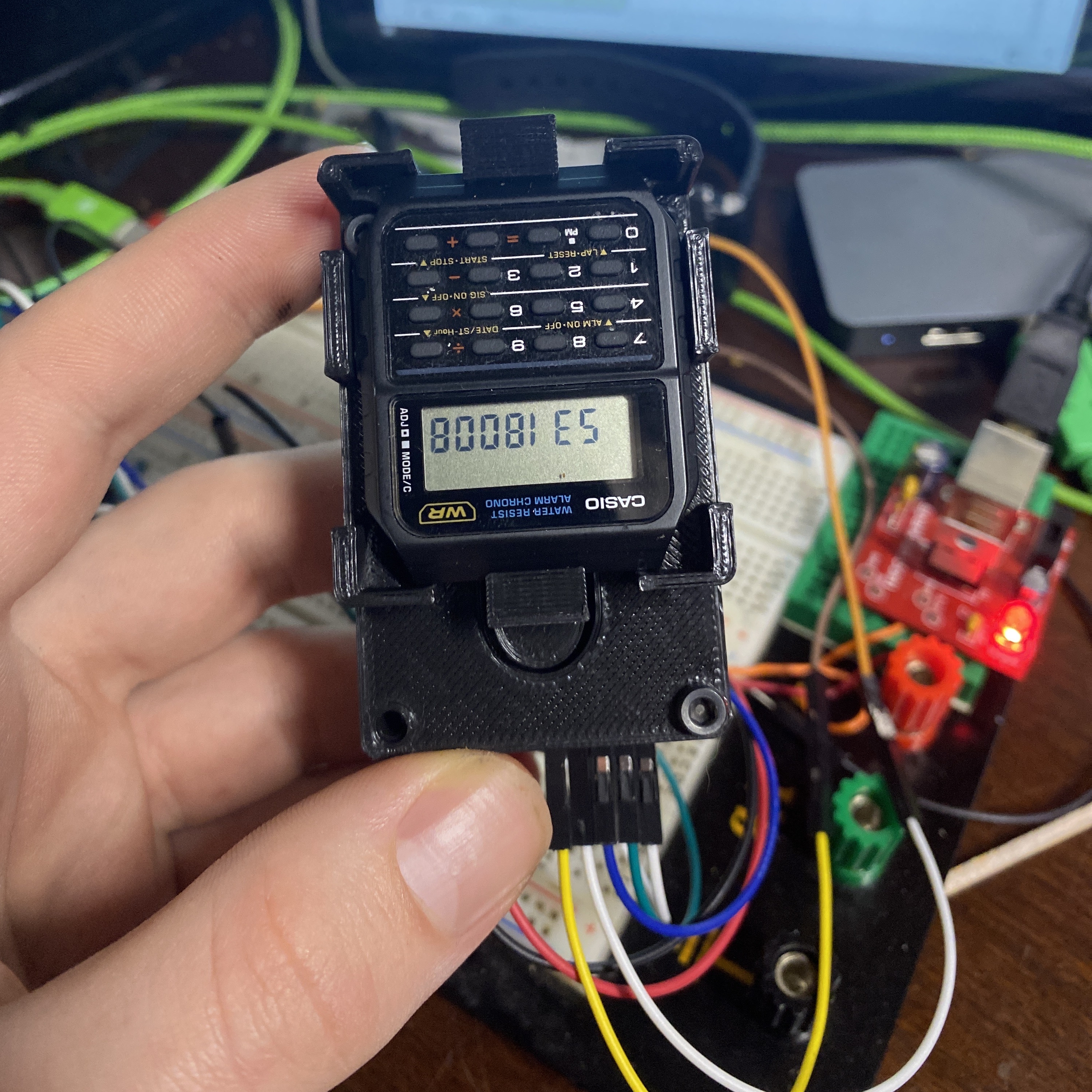
The first version was manufactured by OSHPark using their half height/double copper (0.8mm/2oz) service. This means the board was too thick to fully assemble the watch, but I was still able to start developing the firmware using a 3d-printed jig that connected to the back of the watch using POGO pins.
